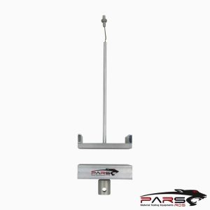
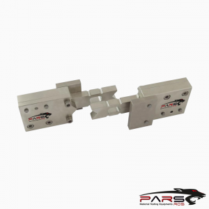
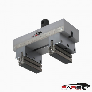
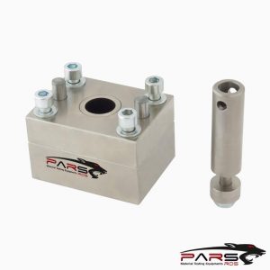
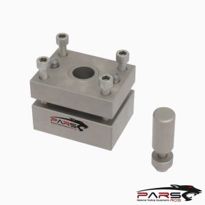
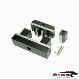
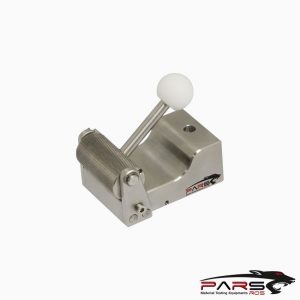
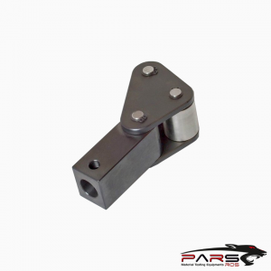
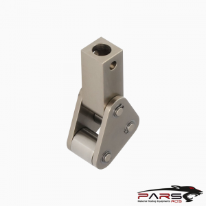
ASTM C1341 Test Fikstürü
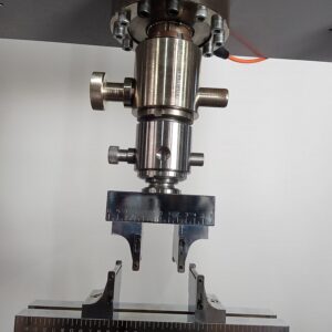
ASTM C1341 covers the determination of flexural properties of continuous fiber-reinforced ceramic composites
Bilgi Almak İçin Lütfen Bizimle İletişime Geçiniz
- Açıklama
- Değerlendirmeler (0)
- TEKNİK ÖZELLİKLER
Açıklama
Açıklama
ASTM C1341 – Standard Test Method for Flexural Properties of Continuous Fiber-Reinforced Advanced Ceramic Composites
ASTM C1341 covers the determination of flexural properties of continuous fiber-reinforced ceramic composites in the form of rectangular bars formed directly
or cut from sheets, plates, or molded shapes. Three test geometries are described as follows:
Test Geometry I—A three-point loading system utilizing center loading on a simply supported beam.
Test Geometry IIA—A four-point loading system utilizing two load points equally spaced from their adjacent support points with a distance between load points of
one half of the support span.
Test Geometry IIB—A four-point loading system utilizing two load points equally spaced from their adjacent support points with a distance between load points of
one third of the support span.
This test method applies primarily to all advanced ceramic matrix composites with continuous fiber reinforcement: uni-directional (1-D), bi-directional (2-D),
tri-directional (3-D), and other continuous fiber architectures.
In addition, this test method may also be used with glass (amorphous) matrix composites with continuous fiber reinforcement.
However, flexural strength cannot be determined for those materials that do not break or fail by tension or compression in the outer fibers.
This test method does not directly address discontinuous fiber-reinforced, whisker-reinforced, or particulate-reinforced ceramics.
Those types of ceramic matrix composites are better tested in flexure using Test Methods C 1161 and C 1211.
Tests can be performed at ambient temperatures or at elevated temperatures.
At elevated temperatures, a suitable furnace is necessary for heating and holding the specimens at the desired testing temperatures.
ASTM C1341 / Apparatus
Testing Machine —Test the flexure specimens in a properly calibrated testing machine that can be operated at constant rates of cross-head motion over
the range required.
The error in the load measuring system shall not exceed 61 % of the maximum load being measured.
The load-indicating mechanism shall be essentially free from inertial lag at the cross-head rate used.
Although not recommended, if the cross-head displacement is used to determine the specimen deflection for the three-point loading geometry, determine
the compliance of the load train (see Appendix X1), so that appropriate corrections can be made to the deflection measurement.
Equip the system with a means for retaining the readout of the maximum load as well as a record of load versus time. Verify the accuracy of the testing machine
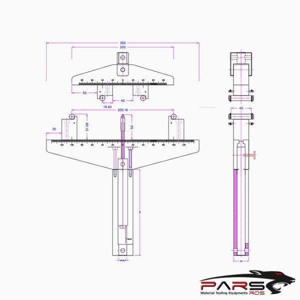
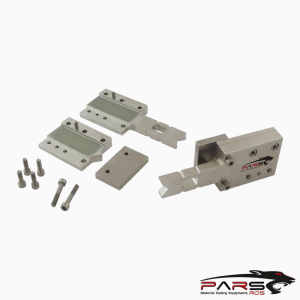
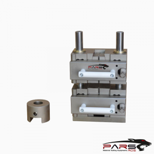
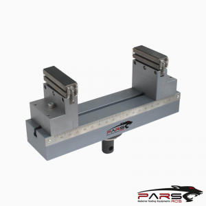
ASTM C1341 /Loading Fixtures—The outer loading span and the desired test geometry determine the dimensions and geometry of the loading fixture.
Select the fixture geometry from one of three configurations: 3-point, 4-point-1⁄4 point, and 4-point-1⁄3 point.
The thickness of specimen to be tested determines the critical outer span dimension (L) of the loading fixture.
The overall dimensions of the specimen and the required loading span are selected based on the specimen thickness, the desired test geometry,
Ensure that the design and construction of the fixtures produces even and uniform loads along the bearing-tospecimen surfaces.
A rigid loading fixture is permitted, if it is designed and aligned so that loads are evenly applied to the test specimen, particularly for four-point loading
geometries.
It is preferred, however, that load fixtures with an articulating geometry be used.
An articulated loading fixture reduces or eliminates uneven loading caused by geometry variations of the specimen or misalignment of the test fixtures.
ASTM C1341 / Semi-Articulating Fixtures—Specimens prepared in accordance with and meeting the parallelism requirement of 9.4 may be tested in
a semi-articulating fixture.
The bearing cylinders shall be parallel to each other within 0.1 mm over their length.
ASTM C1341 /Fully Articulating Fixture—Specimens with slight warp, twist, or bowing may not meet the parallelism requirements of 9.4. It is recommended that
such specimens
be tested in a fully articulating fixture.
The test fixture shall be made of a material that is suitably rigid and resistant to permanent deformation at the loads and temperatures of testing.
The test fixture material shall be essentially inert at the desired test temperatures.
ASTM C1341 / Load Bearings—In both the three-point and four-point flexure test fixtures, use cylindrical bearings for support of the test specimen and for load application.
The cylinders shall be made of a tool steel or a ceramic with an elastic modulus between 200 and 400 GPa and a flexural strength no less than 275 MPa.
The load bearing cylinders shall remain elastic over the load and temperature ranges used.
Ensure that the load bearings have cylindrical surfaces that are smooth and parallel along their length to an accuracy of 6 0.05 mm.
In order to avoid excessive indentation or crushing failure directly under the loading surface, the bearing bearingsurface diameter shall be at least 3.0 mm.
The bearing-surface diameter shall be approximately 1.5 times the beam depth of the test specimen size used.
If the specimen has low throughthickness compressive strength, the cylinder diameter shall be four times the beam thickness to prevent crushing at the load points.
NOTE 1—In such circumstances, however, there is a possible error due to contact-point tangency shift due to the change in loading point as the specimen deflects
during loading.
Position the outer support bearing cylinders carefully such that the support span distance is accurate to a tolerance of 1 %.
The load application bearing for the three-point configuration shall be positioned midway between the support bearings to an accuracy of 1 % of the outer span length.
The load application (inner) bearings for the four-point configurations shall be properly positioned with respect to the support (outer) bearings to an accuracy of
1 % of the outer span length.
For articulating fixtures, the bearing cylinders shall be free to rotate in order to relieve frictional constraints (with the exception of the center-load bearing cylinder
in three-point flexure, which need not rotate).
Note that the outer support bearings roll outward, and the inner loading bearings roll inward.
ASTM C1341 / Deflection Measurement—The test system shall have a means of measuring specimen deflection, appropriate for the load geometry and the test temperature.
The preferred device measures actual deflection at the centerline of the test specimen load span, using direct contact or optical function.
The calibrated range of the deflectometer shall be such that the linear strain region of the material tested will represent a minimum of 20 % of the calibrated range.
The deflectometer shall have an accuracy of 1 % of the maximum deflection measured.
ASTM C1341 / Strain Measurement—The use of strain gages for ambient testing is acceptable provided that the test material surface is smooth with little open porosity
and that the applied strain gage is large enough to cover a representative area of the composite specimen.
Follow the manufacturer’s recommendations regarding application and performance. Strain gages shall not interfere with the deflection measuring device.
ASTM C1341 / Heating Apparatus—For elevated-temperature testing, any furnace that meets the temperature uniformity and control requirements described below
shall be acceptable.
A furnace whose heated cavity is large enough to accept the entire test fixture is preferred.
The furnace shall be capable of establishing and maintaining a constant temperature (within 65°C) during each test period.
Measure the temperature uniformity of the test specimen across the load span section extending from the center to 5 mm inside the outer support points.
The temperature uniformity along the load span shall be within 65°C test temperatures up to and including 500°C and 61 % for test temperatures above 500°C.
In order to determine conformance to the temperature control and uniformity requirements, determine a temperature profile using thermocouples to measure
the specimen temperature at three locations—the specimen center point and two points 5 mm inside the outer support points.
Determine temperature uniformity for all elevatedtemperature testing and recheck the uniformity if any of the following parameters are changed: heating method,
specimen material, sample geometry, or test temperature, or combination thereof.
ASTM C1341 / Temperature Measurement
The use of thermocouples (TC) is recommended and preferred; however, the use of optical pyrometery is acceptable.
For TC measurement, elevated-temperature tests require the placement of one TC at the specimen center.
The sheathed TC should be within 1 mm of the test specimen.
The use of two additional thermocouples at locations 5 mm inside the outer support points is recommended to check for temperature uniformity.
Thermocouples shall be calibrated in accordance with Test Method E 220 with a verified accuracy of 65°C.
ASTM C1341 / Atmosphere Control—The furnace may have an air, inert, or vacuum environment, as required.
If an inert or vacuum environment is used, and it is necessary to apply load through a bellows, fitting, or seal, verify that load losses or errors do not exceed
1 % of the expected failure loads.
ASTM C1341 / Data Acquisition
At the minimum, obtain an autographic record of the applied load and center-point deflection or sample strain versus time for the specified cross-head rate.
Either analog chart recorders or digital data acquisition systems
Referenced Documents
ASTM C 1145 Terminology of Advanced Ceramics
ASTM C 1161 Test Method for Flexural Strength of Advanced Ceramics at Ambient Temperature
ASTM C 1211 Test Method for Flexural Strength of Advanced Ceramics at Elevated Temperatures
ASTM C 1239 Practice for Reporting Uniaxial Data and Estimating Weibull Distribution Parameters for Advanced Ceramics
ASTM C 1292 Test Method for Shear Strength of Continuous Fiber-Reinforced Advanced Ceramics at Ambient Temperatures
ASTM D 790 Test Methods for Flexural Properties of Unreinforced and Reinforced Plastics and Electrical Insulating Materials
ASTM D 2344 Test Method for Apparent Interlaminar Shear Strength of Parallel Fiber Composites by Short Beam Method
ASTM D 3878 Terminology for High-Modulus Reinforcing Fibers and Their Composites4
ASTM E 4 Practices for Force Verification of Testing Machines5
ASTM E 6 Terminology Relating to Methods of Mechanical Testing5
ASTM E 177 Practice for Use of the Terms Precision and Bias inASTM E 220 Test Method for Calibration of Thermocouples by Comparison Techniques
ASTM E 337 Test Method for Measured Humidity with Psychrometer (the Measurement of Wet- and Dry-Bulb Temperatures)
ASTM E 380 Practice for Use of International System of Units (SI) (The Modernized Metric System)
ASTM E 691 Practice for Conducting an Interlaboratory Study to Determine the Precision of a Test Method
*** Before conducting ASTM C1341 , it is important to read the entire specification. Standards can be obtained from appropriate standard authorities.
***PARSROS offers several types of grips and fixtures which will enable you to perform a variety of tests
that are accurate and repeatable.
Değerlendirmeler (0)
“ASTM C1341 Test Fikstürü” için yorum yapan ilk kişi siz olun
Değerlendirme yazabilmek için oturum açmalısınız.


Değerlendirmeler
Henüz değerlendirme yapılmadı.