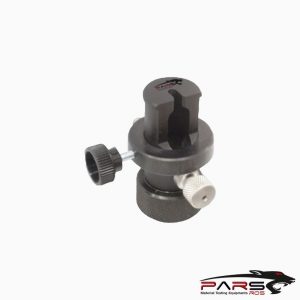
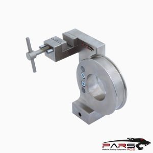
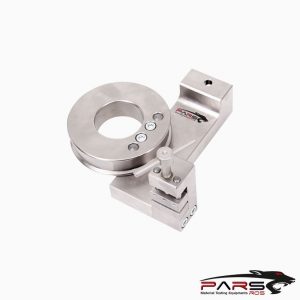
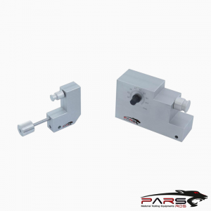
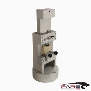
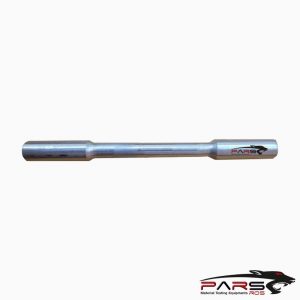
ASTM C1674 Test Fixture
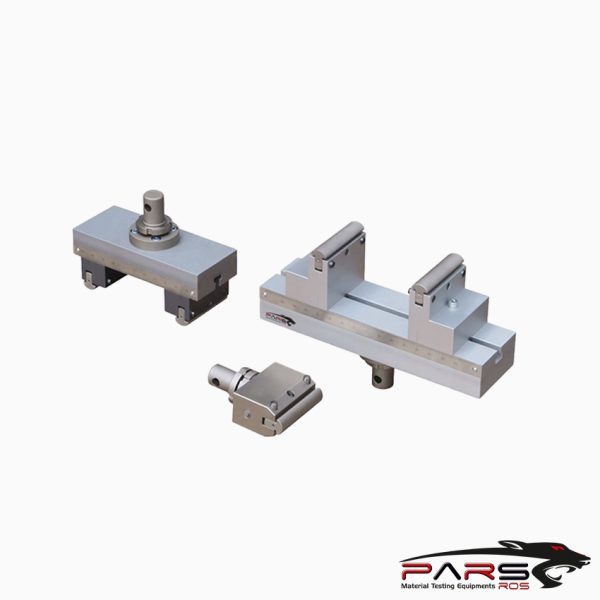
ASTM C1674 covers the determination of the flexural strength (modulus of rupture in bending) at ambient conditions of advanced ceramic structures
Please Contact With Us For More Information
- Description
- Reviews (0)
- TECHNICAL SPECIFICATIONS
Description
Description
ASTM C1674 – cStandard Test Method for Flexural Strength of Advanced Ceramics with Engineered Porosity (Honeycomb Cellular Channels) at Ambient Temperatures
ASTM C1674 covers the determination of the flexural strength (modulus of rupture in bending) at ambient conditions of advanced ceramic structures with
2-dimensional honeycomb channel architectures.
ASTM C1674 / The test method is focused on engineered ceramic components with longitudinal hollow channels, commonly called “honeycomb” channels.
The components generally have 30 % or more porosity and the cross-sectional dimensions of the honeycomb channels are on the order of 1 millimeter 1 mm
or greater.
Ceramics with these honeycomb structures are used in a wide range of applications (catalytic conversion supports (1),2 high temperature filters (2, 3),
combustion burner plates (4), energy absorption and damping (5), etc.).
The honeycomb ceramics can be made in a range of ceramic compositions—alumina, cordierite, zirconia, spinel, mullite, silicon carbide, silicon nitride,
graphite, and carbon.
The components are produced in a variety of geometries (blocks, plates, cylinders, rods, rings).
The test method describes two test specimen geometries for determining the flexural strength (modulus of rupture) for a porous honeycomb ceramic test specimen
Test Method A—A 4-point or 3-point bending test with user-defined specimen geometries, and
Test Method B—A 4-point-1⁄4 point bending test with a defined rectangular specimen geometry (13 mm × 25 mm × > 116 mm) and a 90 mm outer support
span geometry suitable for cordierite and silicon carbide honeycombs with small cell sizes.
The test specimens are stressed to failure and the breaking force value, specimen and cell dimensions, and loading geometry data are used to calculate a nominal
beam strength, a wall fracture strength, and a honeycomb structure strength.
Test results are used for material and structural development, product characterization, design data, quality control, and engineering/production specifications.
The test method is meant for ceramic materials that are linear-elastic to failure in tension.
The test method is not applicable to polymer or metallic porous structures that fail in an elastomeric or an elastic-ductile manner.
The test method is defined for ambient testing temperatures. No directions are provided for testing at elevated or cryogenic temperatures.
ASTM C1674 / Apparatus
ASTM C1674 /Testing Machine—The flexure specimens shall be tested in a properly calibrated mechanical testing machine that can be operated at constant rates of
cross-head motion over the range required with a suitable force sensor.
The error in the force measuring system shall not exceed 61 % of the maximum force being measured.
Verify the accuracy of the testing machine in accordance with Practice ASTM E4.
The force-indicating mechanism shall be essentially free from inertial lag at the cross-head rate used.
Equip the system with a means for retaining the readout of the maximum force as well as a record of force versus time.
Test fixtures are defined for Test Methods A1, A2, and B.
ASTM C1674 / Test Method A1: 4-Point-1⁄4 Point Loading
The specimen rests on two supports and is loaded at two points (by means of two loading bearings), each an equal distance (one quarter of the overall span)
from the adjacent outer support point.
The distance between the loading bearings (the inner gage span) is one half of the complete gage (outer support) span
ASTM C1674 / The Method B
Specimen thickness (d) determines the outer span dimension (L) of the test fixture.
Test fixtures shall be wide enough to support the entire width of the selected specimen geometry.
ASTM C1674 / Test Method A2: 3-Point Loading
The specimen rests on two supports and is loaded at one point (by means of one loading bearing), midway between the two outer support points.)
ASTM C1674 / The Method B
Specimen thickness (d) determines the outer span dimension (L) of the test fixture.
Test fixtures shall be wide enough to support the entire width of the selected specimen geometry.
(Under some cases, e.g. for example, very short specimens, three point loading may be easier to do than the four point loading.)
ASTM C1674 / Test Method B: 4-Point-1⁄4 Point Loading
The outer support span is 90 mm; the inner span is 45 mm. Each inner span point is an equal distance (22.5 mm) from the adjacent outer support point.
Test fixtures shall be wide enough to support the entire width of the selected specimen geometry.
The test fixture shall be made of a material that is suitably rigid and resistant to permanent deformation at the applied forces and that will give a low system
compliance so that most of the crosshead travel is imposed onto the test specimen.
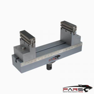
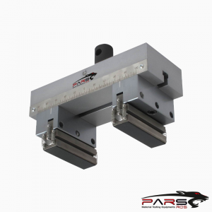
Test fixtures with an articulating geometry shall be used to ensure that the fixtures produce even and uniform loads along the bearing-to-specimen surfaces.
An articulated (full or semi) test fixture reduces or eliminates uneven loading caused by geometric variations of the specimen or misalignment of the test fixtures.
A rigid test fixture is not permitted, because it cannot accommodate non-uniformity and variations in specimen dimensions.
For articulating fixtures, the bearing cylinders shall be free to rotate or rock in order to relieve frictional constraints (with the exception of the center bearing cylinder
in three-point flexure, which need not rotate).
ASTM C1674 / Support/Load Bearings
In both the three-point and four-point flexure test fixtures, use contact bearings with rounded edges for support of the test specimen and for force application.
The length of the contact bearings shall be at least 10 % greater than the specimen width.
The bearing material should be hard enough to minimize abrasion of the bearing surfaces.
NOTE 6—It is recommended that the cylinders be made of a tool steel (case hardened to about HRC 60) or a ceramic with an elastic modulus between 200 and
400 GPa and a flexural strength no less than 275 MPa (40 ksi).
The bearing fixture design shall provide for precise and positive positioning of the bearings with no “slack” or “slop.”
Roller bearings positioned against mechanical stops meet this requirement.
Ensure that the bearings have rounded bearing surfaces that are smooth and parallel along their length to an accuracy of 60.05 mm.
The diameter of the bearing shall be large enough to avoid point load concentrations that produce localized crushing.
Cylindrical bearings commonly have diameters that are 50 to 150 % of the specimen thickness.
NOTE 7—If the specimen has low through-thickness compressive strength such that the failure initiates at the bearing contact surface, the cylinder diameter
should be increased to reduce the force concentration and prevent crushing at the contact/load points.
Alternately the support span can be increased to reduce the force required for fracture.
Position the outer support bearing cylinders carefully such that the support span distance is accurate to a tolerance of 61⁄2 %.
Position the inner support bearing carefully such that the inner support span distance is accurate to a tolerance of 61⁄2 %.
The inner support bearings for the four-point configurations shall be properly centered and aligned with respect to the outer support bearings to an accuracy
of 61⁄2 % of the outer span length.
The center bearing for the three-point configuration shall be centered between the outer support bearings to an accuracy of 61⁄2 % of the outer span length.
Bearings should be replaced when observable abrasive wear occurs on the bearing surface.
If failure cracks initiate at the point of contact between the load bearings and wall stubs/asperities on the test specimen, a narrow strip of compliant, cushioning
material may be placed between the specimen and the full length of the loading bearings/edges.
NOTE 8—Cushioning materials that have been used are PTFE polymer (Teflon®) gasket material, thick compliant construction paper, or thin polyurethane foam.
*** Before conducting ASTM C1674 , it is important to read the entire specification. Standards can be obtained from appropriate standard authorities.
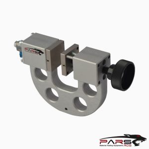
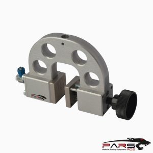
***PARSROS offers several types of grips and fixtures which will enable you to perform a variety of tests
that are accurate and repeatable.
Reviews (0)
Be the first to review “ASTM C1674 Test Fixture”
You must be logged in to post a review.
TECHNICAL SPECIFICATIONS
Please Contact with our engineers so that we can find and offer Best Universal Tensile Test Machines , Grips , Jaws and Other Accessories for your operations


Reviews
There are no reviews yet.