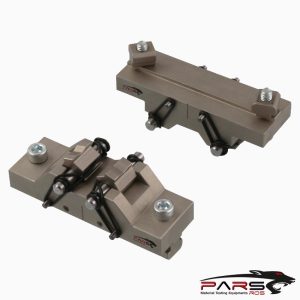
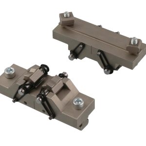
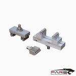
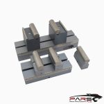
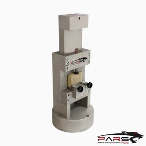
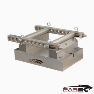
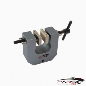
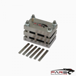
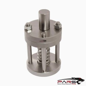
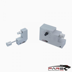
ASTM C1684 Test Fixture
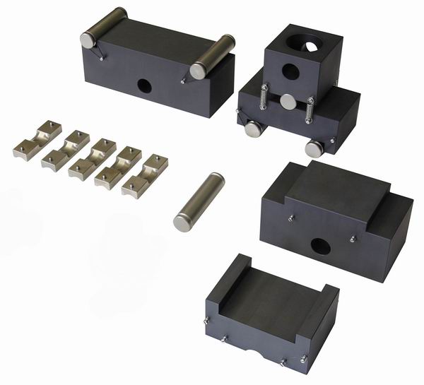
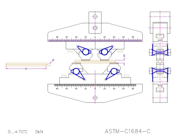
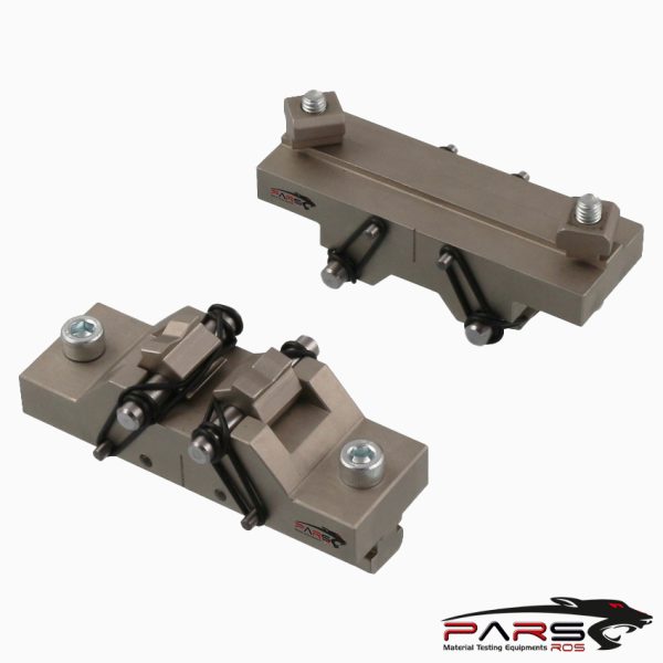
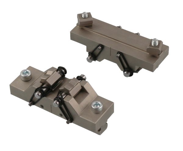
ASTM C1684 is for the determination of flexural strength of rod shape specimens of advanced ceramic materials at ambient temperature.
Please Contact With Us For More Information
- Description
- Reviews (0)
- TECHNICAL SPECIFICATIONS
Description
Description
ASTM C1684- Standard Test Method for Flexural Strength of Advanced Ceramics at Ambient Temperature—Cylindrical Rod Strength
ASTM C1684 is for the determination of flexural strength of rod shape specimens of advanced ceramic materials at ambient temperature.
In many instances it is preferable to test round specimens rather than rectangular bend specimens, especially if the material is fabricated in rod form.
This method permits testing of machined, drawn, or as-fired rod shaped specimens.
It allows some latitude in the rod sizes and cross section shape uniformity.
Rod diameters between 1.5 and 8 mm and lengths from 25 to 85 mm are recommended, but other sizes are permitted.
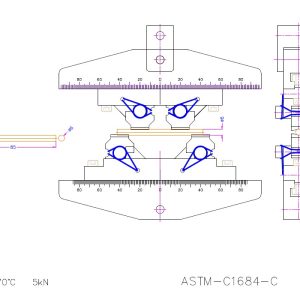
Four-point-1⁄4 point is the preferred testing configuration.
Three-point loading is permitted.
This method describes the apparatus, specimen requirements, test procedure, calculations, and reporting requirements.
The method is applicable to monolithic or particulate- or whisker-reinforced ceramics.
It may also be used for glasses. It is not applicable to continuous fiber-reinforced ceramic composites.
ASTM C1684 / Apparatus
ASTM C1684 / Loading—Specimens may be loaded in any suitable testing machine provided that uniform rates of direct loading can be maintained.
The force measuring system shall be free of initial lag at the loading rates used and shall be equipped with a means for retaining read-out of the maximum
force applied to the specimen.
The accuracy of the testing machine shall be in accordance with Practices ASTM E4.
ASTM C1684 / Four-Point Flexure
Four-point-1⁄4 point fixtures are the preferred configuration. When possible, use one of the outer support and inner loading span combinations
Other span sizes may be used if these sizes are not suitable for a specific round part.
The ratio of the fixture outer span length to the specimen diameter shall not be less than 3.0.
ASTM C1684 / Three-Point Flexure—Three-point flexure may be used if four-point is not satisfactory, such as if the specimens are very short and stubby
and consequently require very large breaking forces in four-point loading.
When possible, use one of the support spans for three-point loading. Other span sizes may be used if these sizes are not suitable for a specific round part.
The outer fixture span length to specimen diameter ratio shall not be less than 3.0.
ASTM C1684 / Loading Rollers—Force shall be applied to the test pieces directly by rollers or alternatively by rollers with cradles
This test method permits direct contact of rod specimens with loading and support rollers.
Direct contact may cause two problems, however. The crossed cylinder arrangement creates intense contact stresses in both the loading roller and the test
specimen due to the very small contact footprint.
The magnitude of the contact stresses depends upon the applied forces, the roller and test specimen diameters, and their elastic properties.
Direct loading by rollers onto the rod test specimens may cause premature test specimen fracture invalidating the test.
Contact stresses may generate shallow Hertzian cone cracks in the test specimen.
Minor cracking at an inner loading point (on the compression-loaded side of the test rod) usually is harmless since it does not cause specimen breakage
and forces are transmitted through the crack faces.
In extreme conditions, however, such as loading of short stubby specimens in 3-point or 4-point loading, the magnitude of the forces and contact stresses
may be great enough to drive a Hertzian crack deep into the test specimen cross section.
Contact cracks at the outer support rollers may be deleterious and cause an undesirable fracture of the specimen, even though these locations are far away
from the inner span in 4-point loading or the middle in 3-point loading.
The propensity for fracture from contact cracks depends upon the test material properties and the testing configuration.
The lower the material’s fracture toughness and the higher the elastic modulus, the more likely that contact cracks will cause premature fracture.
The larger the test specimen diameter for a given test span, the more likely that contact fracture will occur since larger forces are applied to break them.
In other words, short stubby rod specimens are more likely to have problems than long slender rods.
ASTM C1684 allows considerable latitude in the selection of specimen sizes and testing geometries.
If specimens break prematurely from contact cracks, the user shall either: reduce the test specimen diameter, or use longer rod specimens with longer span
test fixtures, or use fixtures with cradles , or shift to three-point loading.
The rollers shall be free to rotate or roll to minimize frictional constraint as the specimen stretches or contracts during loading.
The sole exception is the middle-load roller in three-point flexure which need not rotate.
Note that the outer-support rollers roll outward and the inner-loading rollers roll inward.
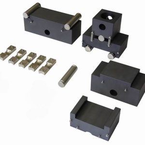
The rollers may roll on a fixture base , they may be mounted in roller assemblies that allow them to rotate.
Cradle inserts may be used in conjunction with loading rollers if necessary to eliminate fractures at the loading points induced by severe contact loading stresses
associated with a round specimen in contact with round loading rollers.
NOTE 1—Fixtures suitable for Test Method ASTM C1161 for rectangular cross section specimens may be used with rod specimens.
Fully-articulating fixtures as defined in ASTM C1161 are not required for rod specimens due to ease of applying force to a cylindrical specimen.
Semi-articulating fixtures as defined in ASTM C1161 are satisfactory for four-point loading of rods.
No articulation is needed for three-point loading. Loading rollers were referred to as “bearings” in Test Method ASTM C1161.
The load application rollers shall be made of hardened steel or a dense strong ceramic.
The portions of the test fixture that support the rollers may need to be hardened to prevent permanent deformation.
The roller length shall be at least three times the specimen diameter. The range of specimen sizes, fixture sizes, and materials permitted by this standard for
rod specimens is so broad that it is difficult to specify a single hardness requirement.
Therefore it is recommended that hardened steel dowel rollers with hardness of HRC 60 or greater be used as the loading and support rollers.
These should be checked after breaking a few specimens and if there is evidence of permanent deformation, then harder rollers should be substituted or
cradles used as per 6.5.
Minor scuff marks, scratches, or small nicks on the rollers do not require the rollers to be replaced.
The roller diameter should be 0.75 to 1.5 times the diameter of the test specimen size.
Smaller diameter rollers may cause excessive contact stresses.
Larger diameter rollers may cause stress errors due to contact point tangency shift as the specimen deflects under load.
All rollers shall be straight and uniform in diameter and have the same diameter to within 60.025 mm.
The rollers shall be carefully positioned such that the spans are accurate within 60.10 mm.
The load application rollers for the three-point configurations shall be positioned midway between the support rollers within 60.10 mm.
The load application (inner) rollers for the four-point configurations shall be centered with respect to the support (outer) rollers within 60.10 mm.
All rollers should be approximately parallel to each other.
NOTE 2—The rollers do not need be as precisely parallel as specified in Test Method ASTM C1161 for fixtures intended to be used for rectangular
flexure specimens.
Unlike rectangular specimens, round rods are much less susceptible to twisting errors.
In general, any fixture suitable for rectangular specimens will have rollers that are sufficiently parallel for round rods.
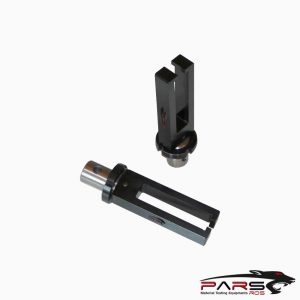
ASTM C1684 / Cradles—If direct contact of loading rollers on the specimen causes fractures at the loading points, then cradle inserts may be used between
the test specimen.
The cradles will relieve most of the contact stresses and eliminate contact crack fractures.
A cradle shall not be used for the middle loading point in three-point loading.
The fixture shall be stiffer than the specimen, so that most of the crosshead travel is imposed onto the specimen.
Fixture compliance should be measured.
An oversized block or rod may be inserted into the fixture and force applied up to the levels expected for a test series.
The load-displacement record can be used to compute the system stiffness or compliance.
*** Before conducting ASTM C1684 , it is important to read the entire specification. Standards can be obtained from appropriate standard authorities.
***PARSROS offers several types of grips and fixtures which will enable you to perform a variety of tests
that are accurate and repeatable.
Reviews (0)
Be the first to review “ASTM C1684 Test Fixture”
You must be logged in to post a review.
TECHNICAL SPECIFICATIONS
Please Contact with our engineers so that we can find and offer Best Universal Tensile Test Machines , Grips , Jaws and Other Accessories for your operations


Reviews
There are no reviews yet.