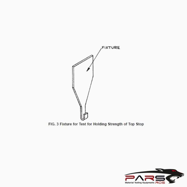
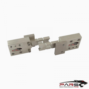
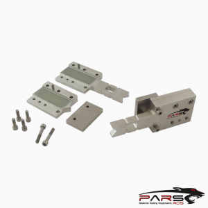
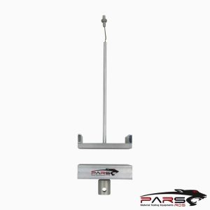
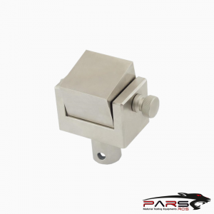
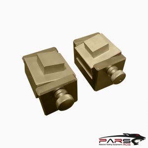
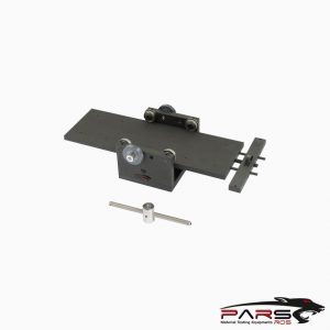
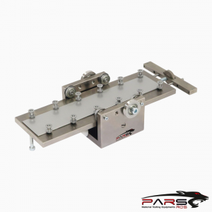
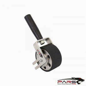
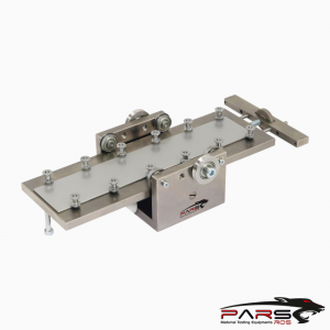
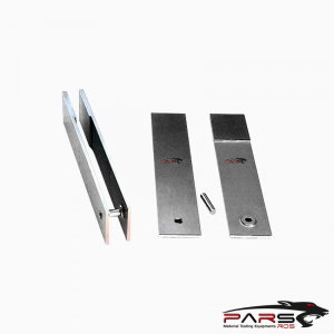
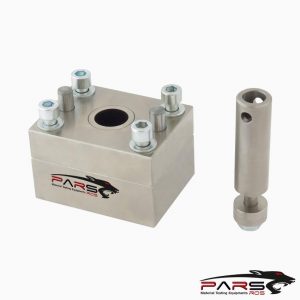
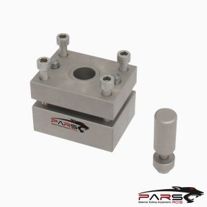
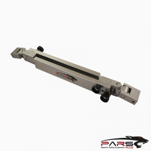
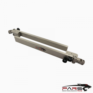
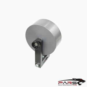
ASTM D2061 Fig.3 Test Fikstürü
ASTM D2061 covers the determination of the strengths for zipper and zipper parts. All methods are not suitable for use with all kinds of zipper.
Bilgi Almak İçin Lütfen Bizimle İletişime Geçiniz
- Açıklama
- Değerlendirmeler (0)
- TEKNİK ÖZELLİKLER
Açıklama
ASTM D2061 – Standard Test Methods for Strength Tests for Zippers
ASTM D2061 covers the determination of the strengths for zipper and zipper parts. All methods are not suitable for use with all kinds of zipper.
ASTM D2061 / HOLDING STRENGTHS OF STOPS
These test procedures are used to determine the holding strengths of various types of zipper stops.
ASTM D2061 / Summary of Test Method
The ability of stops to perform their intended purpose is determined through the use of five different methods which simulate the important stresses encountered
in the end use of zippers.
ASTM D2061 / Significance and Use
Top Stop Holding—This test method may be used to determine top stop attachment strength which measures the ability of the top stop to prevent travel of the
slider beyond the end of the chain.
Bottom Stop Holding, Slider—This test method may be used to determine bottom stop attachment strength, which measures the ability of the bottom stop to
resist failurecaused by stress applied longitudinally to the bottom stop through the slider.
ASTM D2061 / Apparatus
Fixture, as shown in Fig. 3 with a curved end to hook the pull of the slider.
Test Specimen The test specimen shall consist of a completely assembled zipper.
ASTM D2061 / Procedure
In all tests, take care to prevent interference by any locking devices on the slider.
Top Stop Holding—Secure the fixture in the upper clamp of the testing machine and hook the pull of the slider on the fixture .
Position the slider body at the point where normally checked in its free movement by the stop or stops to be tested.
Secure the zipper in the lower clamp of the testing machine .
The distance between the top edge of the lower clamp and mouth of the slider shall be approximately 76 mm (3 in.).
Apply an increasing load until the stop or stops pull off, until the tape breaks, or until failure of some other kind occurs.
Record the nature of the failure and the load at failure to the nearest 2.2 N (0.5 lbf) for values under 222 N (50 lbf) and to the nearest 4.4 N (1 lbf) for
values 222 N and over.
Bottom Stop Holding, Slider—Secure the fixture in the upper clamp of the testing machine and hook the pull of the slider on the fixture (Fig. 3).
Position the slider at the point where normally checked in its free movement by the bottom stop to be tested.
Secure the two stringers in the lower clamp of the testing machine, taking care to equalize the lengths of the two stringers between the clamps.
The angle included between the stringers shall be such as to prevent the catching of elements on the flanges or on the diamond.
The distance between the top edge of the lower clamp and the nearest surface of the slider body shall be approximately 76 mm (3 in.).
Apply an increasing load until the stop pulls off, until the tape breaks, or until failure of some other kind occurs.
Record the nature of the failure and the load at failure to the nearest 2.2 N (0.5 lbf) for values under 222 N (50 lbf) and to the nearest 4.4 N (1 lbf) for
values 222 N and over.
*** Before conducting ASTM D2061 , it is important to read the entire specification. Standards can be obtained from appropriate standard authorities.
***PARSROS offers several types of grips and fixtures which will enable you to perform a variety of tests
that are accurate and repeatable.


Bir yanıt yazın
Yorum yapabilmek için oturum açmalısınız.