


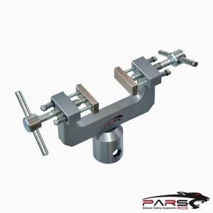
ASTM F1717 Test Fixture

ASTM F1717 – These test methods cover the materials and methods for the static and fatigue testing of spinal implant assemblies in a vertebrectomy model.
Please Contact With Us For More Information
- Description
- Reviews (0)
- TECHNICAL SPECIFICATIONS
Description
Description
ASTM F1717 – Standard Test Methods for Spinal Implant Constructs in a Vertebrectomy Model
ASTM F1717 – These test methods cover the materials and methods for the static and fatigue testing of spinal implant assemblies in a vertebrectomy model.
The test materials for most combinations of spinal implant components can be specific, depending on the intended spinal location and intended method of
application to the spine.
These test methods are intended to provide a basis for the mechanical comparison among past, present, and future spinal implant assemblies.
They allow comparison of spinal implant constructs with different intended spinal locations and methods of application to the spine.
These test methods are not intended to define levels of performance, since sufficient knowledge is not available to predict the consequences of the use of
a particular device.
These test methods set out guidelines for load types and methods of applying loads.
Methods for three static load types and one fatigue test are defined for the comparative evaluation of spinal implant assemblies.
These test methods establish guidelines for measuring displacements, determining the yield load, and evaluating the stiffness and strength of the spinal implant
assembly.
Some spinal constructs may not be testable in all test configurations.
ASTM F1717 / Significance and Use
Spinal implants are generally composed of several components which, when connected together, form a spinal implant assembly.
Spinal implant assemblies are designed to provide some stability to the spine while arthrodesis takes place.
These test methods outline standard materials and methods for the evaluation of different spinal implant assemblies so that comparison between different designs
may be facilitated.
These test methods are used to quantify the static and dynamic mechanical characteristics of different designs of spinal implant assemblies.
The mechanical tests are conducted in vitro using simplified load schemes and do not attempt to mimic the complex loads of the spine.
The loads applied to the spinal implant assemblies in vivo will, in general, differ from the loading configurations used in these test methods.
The results obtained here cannot be used directly to predict in-vivo performance.
The results can be used to compare different component designs in terms of the relative mechanical parameters.
Fatigue testing in a simulated body fluid or saline may cause fretting, corrosion, or lubricate the interconnections and thereby affect the relative performance
of tested devices.
This test should be initially performed dry (ambient room conditions) for consistency.
The effect of environment may be significant.
Repeating all or part of these test methods in simulated body fluid, saline (9 g NaCl per 1000 mL water), a saline drip, water or a lubricant should be considered.
The maximum recommended frequency for this type of cyclic testing should be 5 Hz.
The location of the longitudinal elements is determined by where the anchors are clinically placed against bony structures.
The perpendicular distance to the load direction (block moment arm) between the axis of a hinge pin and the anchor’s attachment points to a UHMWPE block is
independent of anchor type.
The distance between the anchor’s attachment point to the UHMWPE block and the center of the longitudinal element is a function of the interface design between
the screw, hook, wire, cable, and so forth, and the rod, plate, and so forth.
During static torsion testing, the rotation direction (clockwise or counter clockwise) may have an impact on the results.
During static torsion testing, the rotation direction (clockwise or counter clockwise) may have an impact on the results.
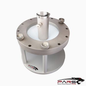
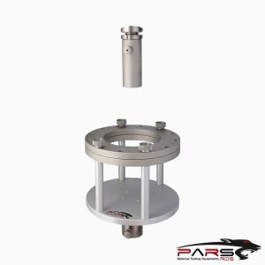
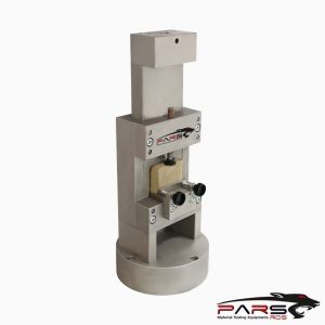
ASTM F1717 / Apparatus
Test machines will conform to the requirements of Practices ASTM E4.
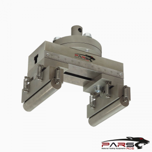
The test apparatus allows multiple loading regimes to be applied to all forms of spinal implant assemblies.
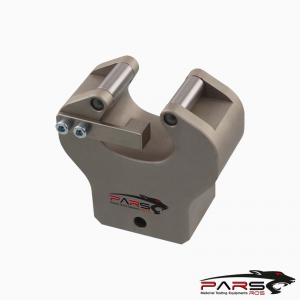
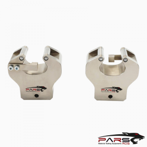
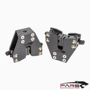
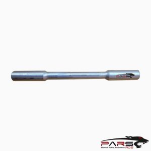
Two pairs of side supports are mounted on the test machine
One pair of side supports attach to the actuator and the second to the load cell.
A mounting plate for one of the sets of side support plates should be free to rotate about the Z axis for the compression bending, tension bending, and fatigue tests.
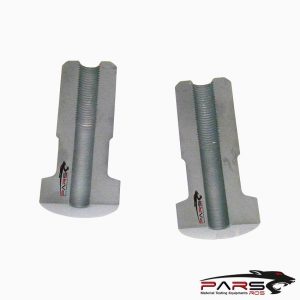
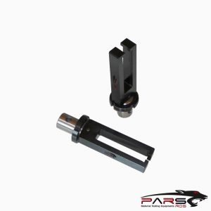
UHMWPE blocks are connected to the side supports via hinge pins.
All testing will simulate a vertebrectomy model via a large gap between the two UHMWPE blocks.
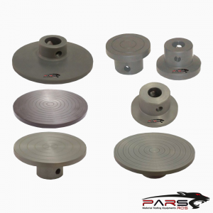
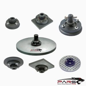
Select the appropriate design of the UHMWPE blocks to facilitate testing of the spinal implant assembly in a manner that simulates the specific clinical indication
at the intended spinal location.
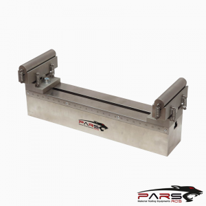
The testing machine and the apparatus used in the static compression bending, static tension bending, and compression bending fatigue tests apply load in
the Z direction without constraining rotation in the X-Y plane.
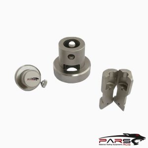
The hinge pin in the apparatus allows rotation in the X-Z plane during the static compression bending, static tension bending, and compression bending
fatigue tests.
The compression bending fatigue test will use the same test configuration as static compressive bending.
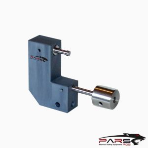
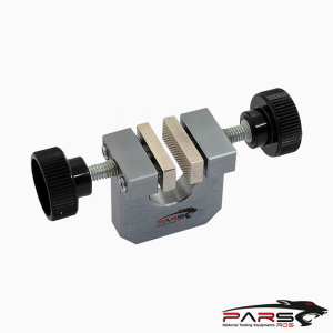
The testing machine or the apparatus used in the static torsion test applies torque about the Z axis without constraining displacement in the Z direction.
Aluminum blocks shall be placed in the apparatus to prevent rotation in the X-Z plane during the static torsion tests.
The total clearance between an aluminum block, an UHMWPE block, and a base plate will not exceed 0.10 mm.
*** Before conducting ASTM F1717 , it is important to read the entire specification. Standards can be obtained from appropriate standard authorities.
***PARSROS offers several types of grips and fixtures which will enable you to perform a variety of tests
that are accurate and repeatable.
Reviews (0)
Be the first to review “ASTM F1717 Test Fixture”
You must be logged in to post a review.
TECHNICAL SPECIFICATIONS
Please Contact with our engineers so that we can find and offer Best Universal Tensile Test Machines , Grips , Jaws and Other Accessories for your operations
Reviews
There are no reviews yet.