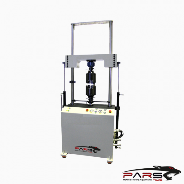
Servo Hydraulic Fatique Testing Machine
STANDARDS
ISO 12106:2017 , ISO 1099 , ISO 4965-1, ISO 4965-2, AFNOR A 03-403:1990 , BS 7270:2006 , ASTM E 606-12, ASTM C1368 , ASTM C394 , ASTM D3479 , ASTM D7774 ,
ASTM E2207 , ASTM E2368 , ASTM E2714 , ASTM E466 , ASTM E467 , ASTM E606 , ASTM E647 , ASTM F1612 , ASTM F1717 , ASTM F1798 , ASTM F1800 , ASTM F1820 ,
ASTM F2118 , ASTM F2193 , ASTM F382 , ISO 14801 , ISO 15024 , ISO 22675 , ISO 7206 , NASM 1312-11
Please Contact With Us For More Information
- Description
- Reviews (0)
- TECHNICAL SPECIFICATIONS
Description
Description
| Product Code |
Product Description |
| PRS-SHFAT | Servo Hydraulic Fatigue Testing Machine |
Servo Hydraulic Fatique Testing Machine
STANDARDS
ISO 12106:2017 , ISO 1099 , ISO 4965-1, ISO 4965-2, AFNOR A 03-403:1990 , BS 7270:2006 , ASTM E 606-12, ASTM C1368 , ASTM C394 , ASTM D3479 , ASTM D7774 ,
ASTM E2207 , ASTM E2368 , ASTM E2714 , ASTM E466 , ASTM E467 , ASTM E606 , ASTM E647 , ASTM F1612 , ASTM F1717 , ASTM F1798 , ASTM F1800 , ASTM F1820 ,
ASTM F2118 , ASTM F2193 , ASTM F382 , ISO 14801 , ISO 15024 , ISO 22675 , ISO 7206 , NASM 1312-11
Fatigue Testing
Fatigue is the progressive, localized, permanent structural change that occurs in materials subjected to fluctuating stresses and strains that may result in cracks or
fracture after a sufficient number of fluctuations.
Fatigue fractures are caused by the simultaneous action of cyclic stress, tensile stress and plastic strain. If any one ofthese three is not present, fatigue cracking will
not initiate and propagate.
The cyclic stress starts the crack; the tensile stress produces crack growth (propagation). Although compressive stress will not cause fatigue, compression load may do so.
The process of fatigue consists of three stages
Initial fatigue damage leading to crack nucleation and crack initiation
Progressive cyclic growth of a crack (crack propagation) until the remaining uncracked cross section of a part
becomes too weak to sustain the loads imposed
Final, sudden fracture of the remaining cross section
Classification of Servo Hydraulic Fatique Testing Machine
Fatigue test specimens are primarily described by the mode of loading:
Direct (axial) stress
Plane bending
Rotating beam
Alternating torsion
Combined stress
Testing machines, however, may be universal type machines that are capable of conducting all of the above modes of loading, depending on the fixturing used.
Servo Hydraulic Fatique Testing Machine – Components
Whether simple or complex, all fatigue testing machines consist of the same basic components:
A load train, controllers, and monitors.
The load train consists of the load frame, gripping devices, test specimen, and drive (loading) system. Typical load train components in an electrohydraulic axial
fatigue machine
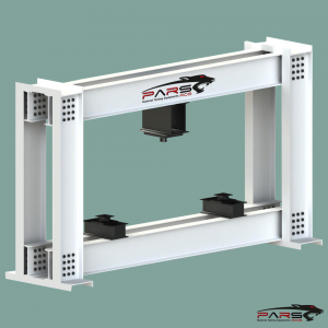
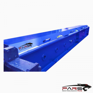
The load frame is the structure of the machine that reacts to the forces applied to the specimen by the drive system.
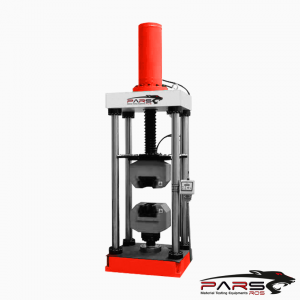
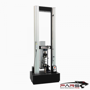
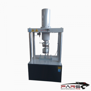
ParsRos Servo Hydraulic Fatigue Testing Machine can perform a wide variety of low and high cycle fatigue, crack propagation, fracture toughngss and other
dynamic tests.
ParsRos Servo Hydraulic Fatigue Testing Machines have a modular design that make easy system standardization and providing system stability and reliability.
It has a modular design. They are designed for the most demanding test applications .
They are used for low and high frequency dynamic tests .
*** ParsRos Servo Hydraulic Fatigue Testing Machines are manufactured in capacities between 10kN and 1000kN.
**** Higher capacities are also available according to special requirements
They can be manufactured as a without size limit.
According to test samples ; Width, depth, height can be adjusted
Test&Motion™ Dynamic Testing Software provides the backbone for running many dynamic tests.
Other application specific software module allows other standardized tests to be run.
These dynamic systems, when combined with Test&Motion™ and appropriate accessories, are ideal for running a variety of static tensile, compression, flexure,
peel, tear and friction tests.
Each system can be readily configured with appropriate sized servo valve, manifold and hydraulic power unit to suit the particular application.
**** All systems are equipped with the advanced features of the “DOLI” (German) digital controller,
Console Software and unique fatigue-rated load cells.
Load cells, jaws and test apparatus can be developed and each test and according to the test method Jaws and grips can be manufactured by ParsRos Engineers .
Computer software is suitable for dynamic (cyclic) tests. Software can make load, elongation and strain-controlled tests.
The Software is suitable for entering unlimited test parameters.
Servo Hydraulic Fatique Testing Machine – LOAD FRAME
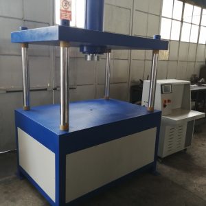
The loading body has a 2-column structure or a 4-column structure for high-capacity testing. Columns are chrome plated and do not wear.
The crosshead is moved by hydraulic force and moves along the columns with precise bearing.
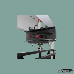
Bidirectional hydraulic piston is mounted on the lower body or upper crosshead and aligned to the pull jaws.
Piston guidance system is located externally in the columns, or anti-rotation system is placed internally.
The upper pulling jaws are mounted in series on the top plates with load cells.
The columns on the body are tested by exceeding 40% of the maximum capacity so that a rigid body is reached.
Servo Hydraulic Fatique Testing Machine – Elongation Measurement System
Elongation measurement and control is fulfilled with frictionless (non-contact) displacement sensors
The displacement sensor sensitivity is 1μm.
Servo Hydraulic Fatique Testing Machine – Load Measurement System
Load measurement and control is carried out with class ± 0,5% fatigue-rated load cell.
Load cell is suitable for dynamic cycle tests.
The system automatically identifies, configures the loadcell and it stores calibration values in its memory.
It provides effective timing and safety against overload.
Reviews (0)
Be the first to review “Servo Hydraulic Fatique Testing Machine”
You must be logged in to post a review.
TECHNICAL SPECIFICATIONS
Capacities available: 50kN-100kN-300kN-500Kn ( **** Contact with us for other capacities )
Moog two stage dynamic servo valve with high flow rate and high step response
Doli dynamic controller; 5 kHz data acquisition or Moog test controller;10 kHz data acquisition
Doli LCD remote control console with emergency stop button
Doli Test & Motion Software with Dyna Pack
Fatigue-Rated load cell accuracy class ±0.5%
Non-contact MTS position sensor, accuracy 0.001 mm
Accumulators for the best dynamic performance
Piston stroke 300 mm (Different stroke range available on request)
Double acting, low-friction piston



Reviews
There are no reviews yet.